The Insitute of Energy Systems and Technology at TU Darmstadt performs chemical looping combustion tests in a 1 MWth CFB plant. Ilmenite will be used as bed material circulating between the two reactors. The fuel feed will start with 100 % lignite and the fraction of waste in the fuel will be increased stepwise, until 100 % waste-derived fuels (RDF) is reached. After each change in fuel composition, the plant is continuously operated for at least 8 hours until a steady-state condition is reached. After reaching steady-state condition, the operating conditions (temperature, pressure drop, fluidization velocity, etc.) of the two reactors are varied to optimize the plant performance with respect to CO2 capture efficiency and gas conversion.
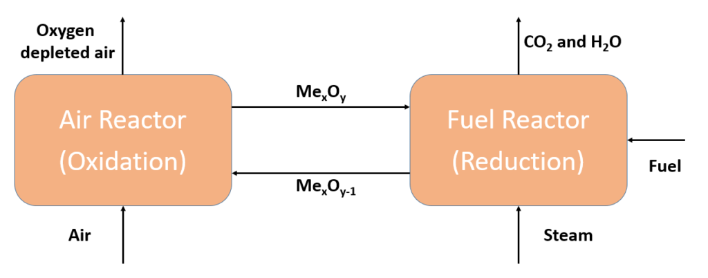 A simplified flow diagramm of the chemcial looping combustion process can be seen on the right handside. The system consists of two coupled reactors. In the air reactor, which is also called the oxidation reactor, reduced metal oxide (MexOy-1) is mixed with ambient air. The following exothermic reaction takes place:
MexOy-1 + 0.5*O2 → MexOy
The oxygen depleted air and the metal oxide (MexOy) are separated in a cyclone and the metal oxide is transported to the fuel reactor. In the second reactor, the metal oxide releases the oxygen, as can be seen in the following endothermic reaction:
MexOy → MexOy-1 + 0.5*O2
The released oxygen reacts with the added fuel and steam in exothermic reactions to carbon monoxide and water. The reduced metal oxide is transported back to the air reactor after being separated from the flue gas. The flue gas can be cooled down in a separate step where the water condenses and pure CO2 is left over, which can be used as input material further downstream.